NOTE: this will only work with HamVoip image. The ASL image does not have the command line software control needed to assert COS
I've wanted to build a radio-less node because sometimes it's easier and makes more sense than a radio-based node. Additionally, sometimes iaxRpt is a pain (e.g. fails to register with Asterisk, network latency issues, etc). And let's face it, talking into a microphone is way cool than talking into your phone.
It must be said -- by Me -- that sound fob modification is foolish -or- I'm not patient or skillful enough to make tiny solder joints. Most importantly, the Pi has perfectly awesome GPIO pins for a good reason: they are to be used for input/output to interface to physical devices. If you want to solder tiny wires to small chips on the fob, please have at it and I immensely respect your skills. But after having a modified fob that I bought fail on me, I think it's a clumsy workaround. Additionally, I suspect the fob mods increase potential for QRM, as I hear it on lots of such nodes.
Parts is parts
RaspberryPi 3A+ -- my most favorite Pi board aside from the PiZero. Does the job of the 3B+ without the latter's power management (undervoltage) issues and with only the single USB port needed. If you need an ethernet connection, obviously grab the 3B+
Syba Sound fob CM119 chipset UNMODIFIED -- plug this into the Pi running HamVoIP and audio is just automatically piped out by default. That's a great sign. Amazon Link (2021-09)
Microphone -- for the talkie talkie. I used a Juentai version of the standard Kenwood KMC-32. It is essentially the same mic but with different keypad layout. The pinout is exactly the same. I chose this because it has 4 convenient wires: PTT, PTT ground, Mic Audio, Mic ground. That's very easy to wire up to the GPIO pins and the sound card.
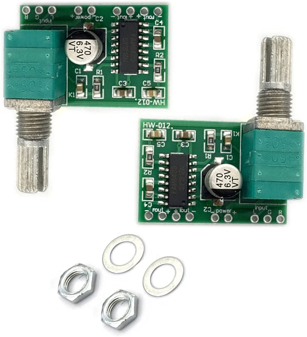
Audio amplifier board -- 3 watts output, two channel, tiny 30mm X 22mm X 16mm size. The sound fob's audio output will not drive anything more than headphones. For noisy shack environments, a small amp is needed. This particular one is conveniently powered by 5V directly from the Pi GPIO pins.
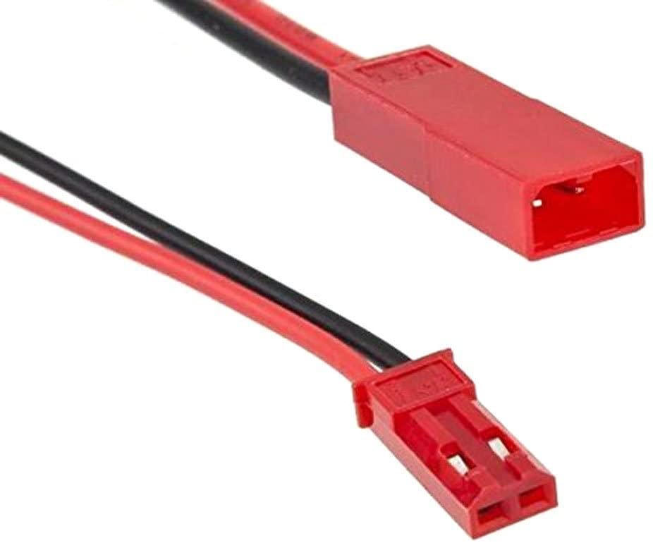
JST connector pigtails -- for connecting to the GPIO pins. [Image]
A box to put it all in. There will be wires. Make sure the box is large enough for comfortable fit and assembly.
Hardware Assembly
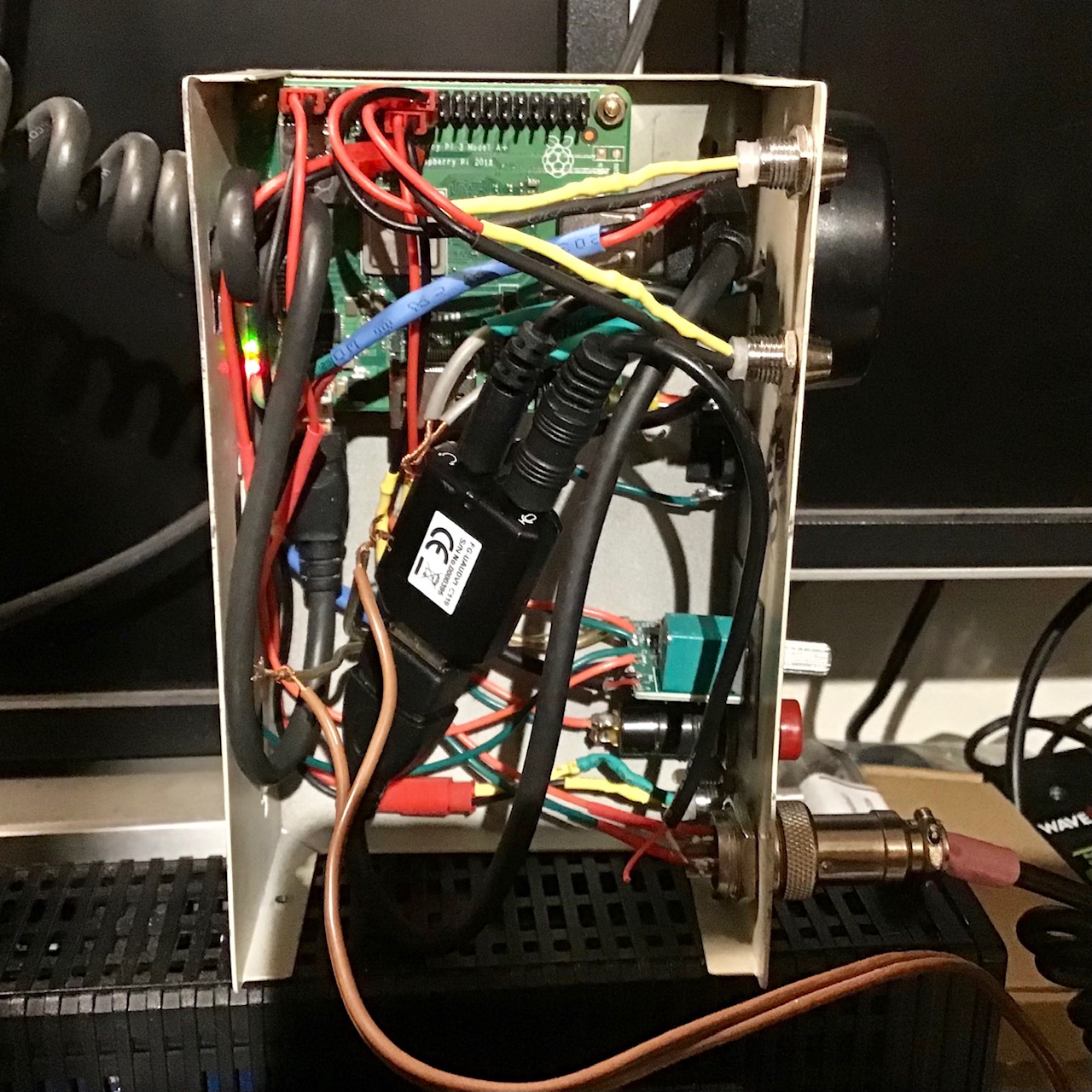
Following are a few pictures of the enclosure and wiring. Click to embiggen.
The Case. A recycled 1980s-era SVGA switch box. I've fallen in love with these as project boxes. The main switch has been replaced by the amplifier volume knob. I drilled holes for a 5-pin mic connector, LEDs, headphone jack, and a gratuitous red button (function TBD).
I suppose I could have found an RJ-45 to hook up the microphone and that would have been easier. But I wanted the old school look of the round, metal connectors.
LEDs as follows:
Yellow LED below mic connector indicates power on. I may modified it to be some sort of heartbeat or connection status LED in the future.
Green LED above left of speaker indicates "Receive", namely that signal is coming in from the internet connection. In Asterisk configuration parlance, this is actually called transmit because a node radio would transmit the signal.
Red LED above right of speaker indicates "Transmit, namely that I am talking into the internet connection. In Asterisk configuration parlance, this is actually called receive because a node radio was receiving signal.
Gloriously Stock Sound Fob -- I soldered two wires (one channel plus ground) of a 3.5mm TRS stereo plug pigtail to two pins on the 5-pin panel mount connector. The plug plugs into the microphone jack on the sound fob. A second 3.5mm TRS stereo plug goes from the sound fob's headphone jack to the left, right, and ground solder points on the amplifier. That's it for the sound fob!
Owing to the placement and fit of the Pi, I had to use a USB extension cable to connect the CM119. Avoid this if you can; Raspberry Pis have in my experience been notoriously and frustratingly picky about working with USB extensions.
The Amplifier. The tiny amp has stereo inputs and outputs, so one output channel goes to the built-in speaker while the other goes to a headphone jack to connect external headphones if desired. Amazon has tons of variations of these, all based on some variation of the PAM8403 chip. I chose one that could specifically be powered by 5v so that I could power it direclty off of the Raspberry Pi GPIO.
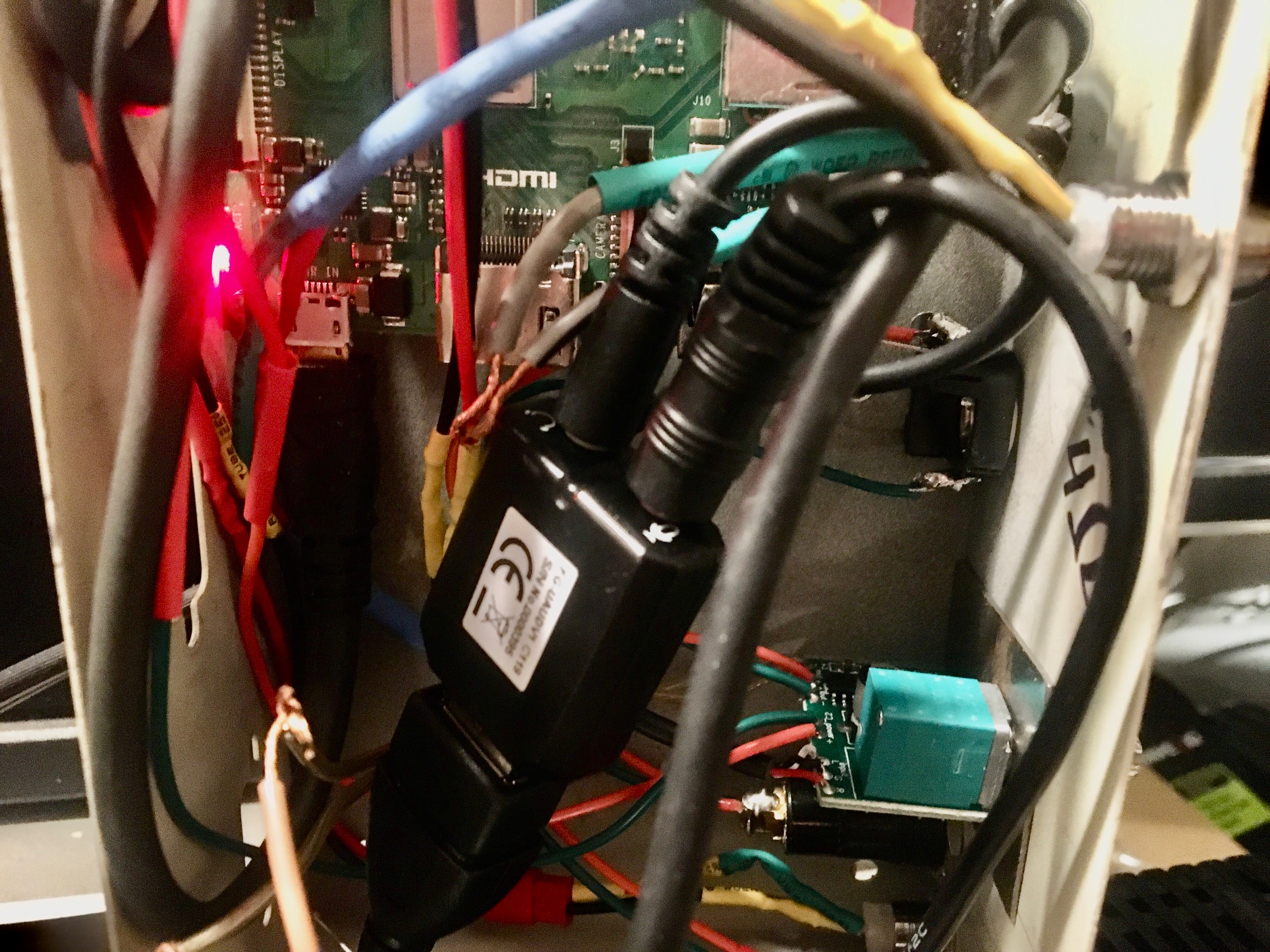
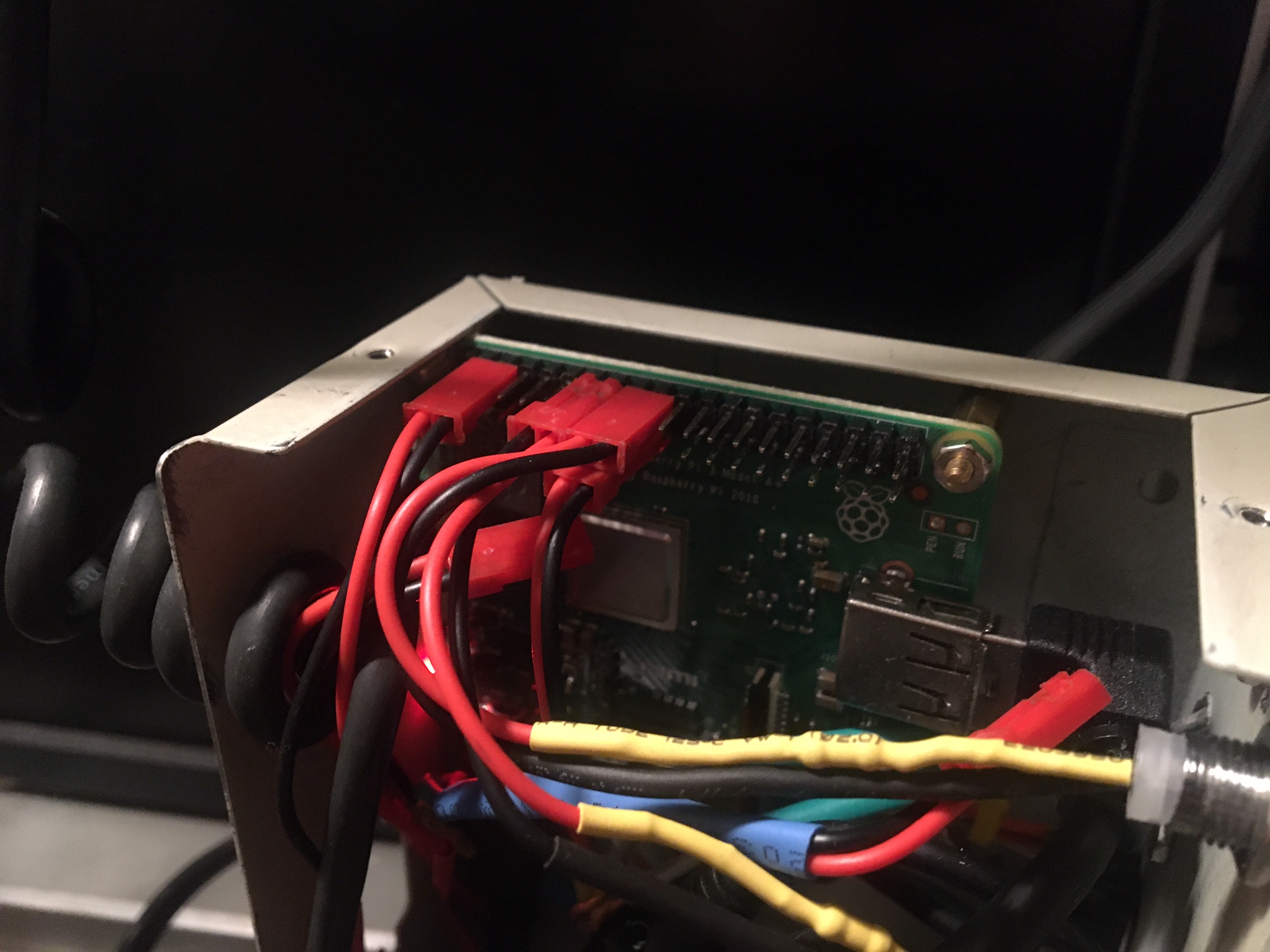
Wire nest. Shockingly, there is still quite a bit of space inside despite the mess of wires.
The hole for one of the SVGA connectors in back provides convenient access to the Pi SD card. This is why I oriented the Pi as I did and used a USB extension. Not having the SD card accessible is a major pain when you need to get at it later.
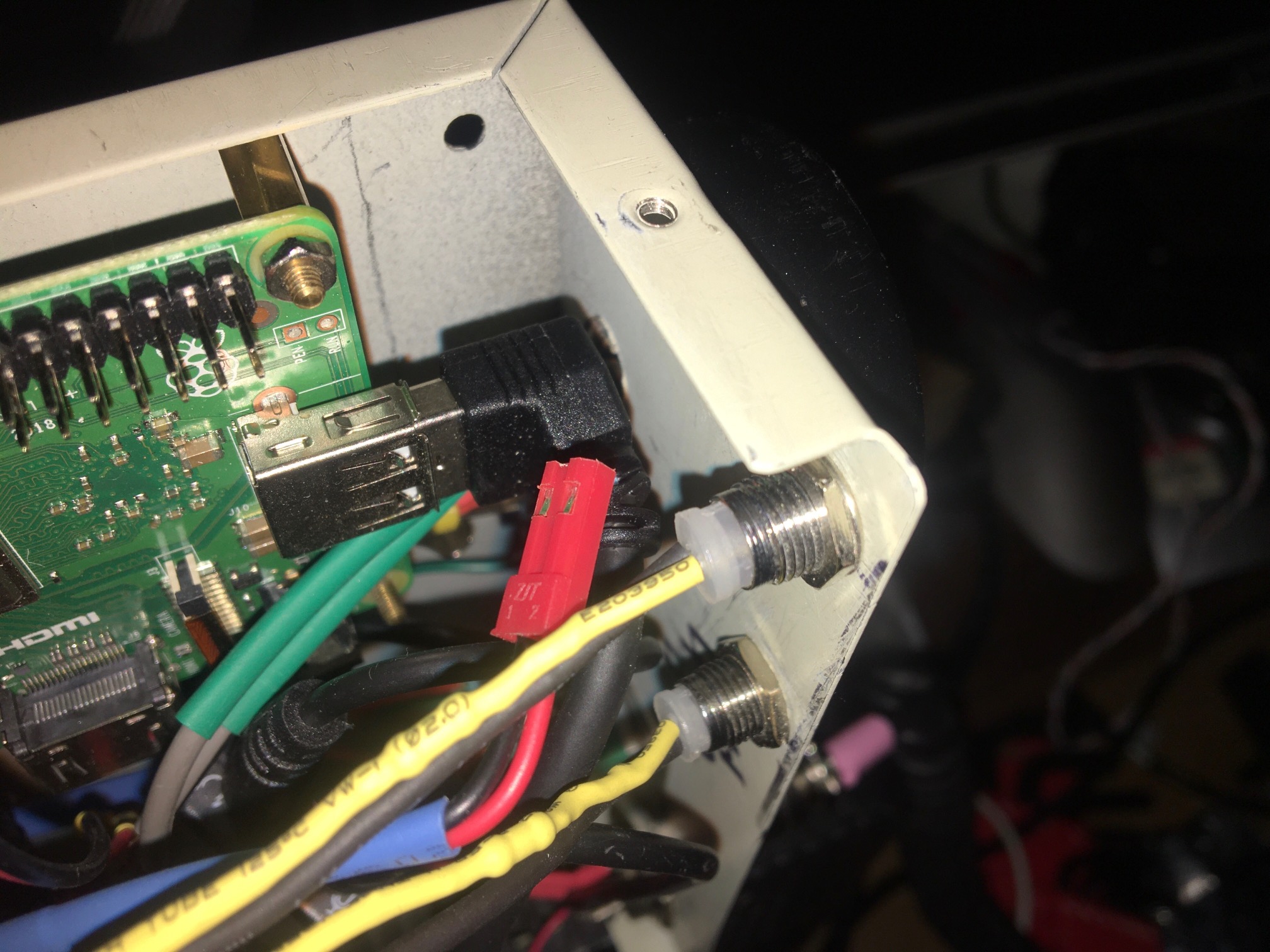
JST GPIO connections All non-audio signalling is accomplished via GPIO. The LEDs are connected to GPIO with on inline resistor on one of the legs. Resistor values can be 220, 330, 470 ohm.
The PTT activated COS signal only uses two GPIO pins: a 3.3 volt positive and a generic I/O pin that a script (see below) pulls to ground using the Pi's built-in pull up/down resistors. When PTT is pressed, the I/O pin is pulled high. The script reads that state and calls the usb-tune-menu command to assert COS. This tells Asterisk to pass mic audio into the internet connection. More on the script in the next section.
In this image, connections are as follows:
Physical Pins 4 6 :: to 5 volt power to amplifier
Physical Pins 14 16 :: to Green LED "RX"
Physical Pins 18 20 :: to Red LED "TX"
Physical Pins 17 19 :: from mic PTT, COS detect THIS IS THE HARDWARE MAGIC
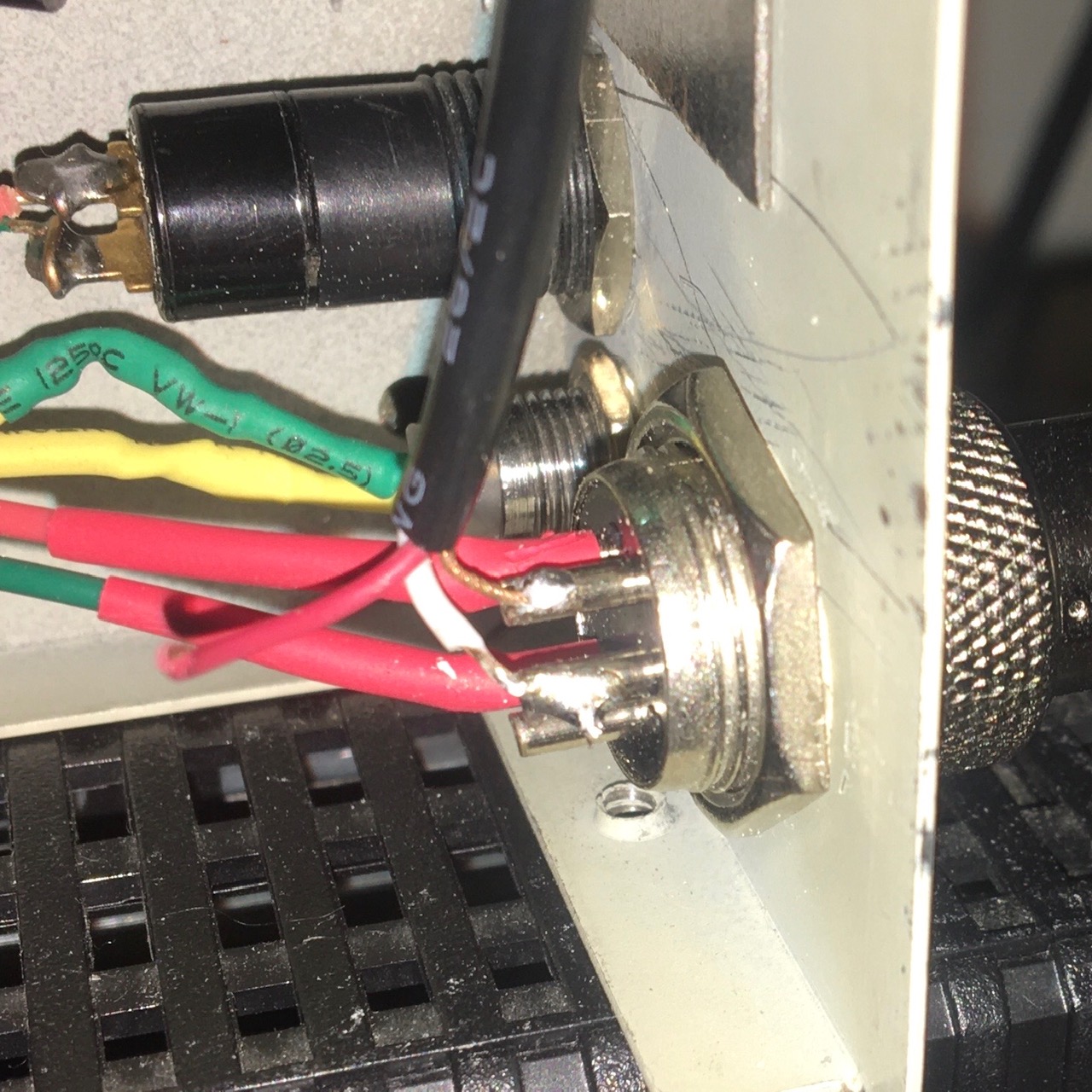
Mic Connector, old school. Five pin microphone connector handles the following signals from the micrphone itself: PTT, PTT ground, Mic Audio, Mic Ground, +8VDC.
I have not yet tried applying 5VDC to the 8V pin, but I am hoping 5V will be sufficient to make the DTMF keypad usable.
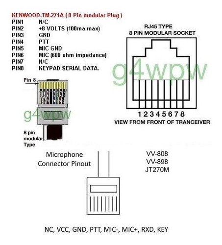
KMC-32 Microphone pinout. I am not using a genuine Kenwood KMC-32, the mic that is found with the TM-v71A, D710,TM-271,TM-281, and other Kenwoods. However, the Kenwood pinout seems to have become the de facto standard for many Chinese radios. This Juentai is no exception; it's the same pinout. I like this style because it has separate grounds for PTT and Mic Audio, at least at the pins. And it's a fine microphone with a proper PTT action unlike those mushy Yaesu mics.
If you are using an RJ-45, just breakout pins 3,4,5,6. Pins 5 and 6 go to the sound card mic input. Pins 3 and 4 go directly to the GPIO. Since we are relying on the Pi's built-in pulldown resistors, there's no need for a complicated circuit with external pull-down.
Software Configuration and Control
Configure rpt.conf Events stanza with text in RED if you desire RX/TX LEDs. More in-depth information about wiring LEDS as well as scripting the Pi to turn them on/off and configuring Asterisk to call the scripts can be found at this link.
You may skip this if you are only using GPIO for PTT/COS.
Install script for handling COS
This is the secret sauce that makes the magic happen. It's quick and dirty... and has possible security concerns when run as root and is outside a firewall. But it works and is less concerning if the node is inside your home and not accessible for log in from the outside world. (note to self: I should rewrite this in C anyway and run it as a compiled binary.) Direct link to script is [here].
Set script to run automatically at boot
There are several ways to do this. This easiest way is to throw the following line into your crontab by typing crontab -e, adding the line, and saving it. It will automatically start every time the machine boots.
Adjust settings in simpleusb-tune-menu
toggle RX Boost Mode to Enabled
Set RX Voice Level (using display) to appropriate levels
Set Transmit A Level
Without RX Boost Mode, I had to bump RX Voice Level up to 950. But when I turned on RX Boost Mode, I could cut back RX Voice Levels significantly. Do whatever yields reasonable audio reports.
Adjust Set Transmit A Level (or presumably Set Transmit B Level depending on which stereo output??) so that you get decent, desire audio levels at the speaker. Depending on your speaker impedance, even the amplifier may not provide sufficient audio levels. So experiment with the settings to something that works for you.